Friday, November 4, 2011

Cisco 3


CCNA online (Part 4)RIP Routing Information Protocol


RIP ROUTING FUNDAMENTALS

RIP stands for Routing Information Protocol.
RIP is a dynamic, distance vector routing protocol and was developed for smaller IP based networks. As mentioned earlier, RIP calculates the best route based on hop count.
There are currently two versions of RIP protocol.
  • RIPv1, and
  • RIPv2
RIPv1: RIP version 1 is among the oldest protocols. 
Limitations of RIPv1:
1. Hop Count Limit: Destination that is more than 15 hops away is considered unreachable by RIPv1.
2. Classful Routing Only: RIP is a classful routing protocol. RIPv1 doesn't support classless routing. RIP v1 advertises all networks it knows as classful networks, so it is not possible to subnet a network using RIP v1.
3. Metric limitation: The best route in RIP is determined by counting the number of hops required to reach the destination. A lower hop count route is always preferred over a higher hop count route. One disadvantage of using hop count as metric is that if there is a route with one additional hop, but with significantly higher bandwidth, the route with smaller bandwidth is taken. This is illustrated in the figure below:

The RIP routed packets take the path through 56KBPS link since the destination can be reached in one hop. Though, the alternative provides a minimum bandwidth of 1MBPS (though using two links of 1MBPS, and 2MBPS each), it represents 2 hops and not preferred by the RIP protocol.

FEATURES OF RIP V2:

RIP v2 is a revised version of its predecessor RIP v1. The following are the important feature enhancements provided in RIPv2:
1. RIPv2 packets carry the subnet mask in each route entry, making RIPv2 a classless routing protocol. It  provides support for variable-length subnet masking (VLSM) and classless addressing (CIDR).
2. Next Hop Specification: In RIPv2, each RIP entry includes a space where an explicit IP address can be entered as the next hop router for datagrams intended for the network in that entry.
For example, this field can be used when the most efficient route to a network is through a router that is not running RIP. Since, that a router will not exchange RIP messages, explicit Next Hop field allows the router to be selected as the next hop router.

3. Authentication: RIPv1 does not support authentication. This loophole may be used maliciously by hackers, that may resulting in delivering the data packets to a fictitious destination as determined by the hacker. RIPv2 provides a basic authentication scheme, so that a router can accept RIP messages from a neighboring router only after ascertaining its authenticity.
4. Route Tag: Each RIPv2 entry includes a Route Tag field, where additional information about a route can be stored. It provides a method for distinguishing between internal routes (learned by RIP) and external routes (learned from other protocols).

LIMITATIONS OF RIP V2:

One of the biggest limitations of RIPv1 still remains with RIPv2. It is hop count limitation, and metric. The hop count of 16 still remains as unreachable, and the metric still remains hop count. A smaller hop count limits the network diameter, that is the number of routers that can participate in the RIP network.
Example Question:
While the packet travels from source to destination through an Internetwork, which of the following statements are true? (Choose 2 best answers).
A. The source and destination hardware (interface) addresses change
B. The source and destination hardware (interface) addresses remain constant.
C. The source and destination IP addresses change
D. The source and destination IP addresses remain constant.
Ans. A, D
Explanation: While a packet travels through an Internetwork, it usually involves multiple hops. It is important to know that the logical address (IP address) of the source (that created the packet) and destination (final intended destination) remain constant, whereas the hardware (interface) addresses change with each hop.

Cisco 2


CCNA online (Part 6) OSPF Routing Fundamentals


OSPF ROUTING FUNDAMENTALS

OSPF stands for Open Shortest Path First.
Definition: OSPF is a routing protocol used to determine the best route for delivering the packets within an IP networks. It was published by the IETF to serve as an Interior Gateway Protocol replacing RIP. The OSPF specification is published as Request For Comments (RFC) 1247.
Note that OSPF is a link-state routing protocol, whereas RIP and IGRP are distance-vector routing protocols. Routers running the distance-vector algorithm send all or a portion of their routing tables in routing-update messages to their neighbors.
OSPF sends link-state advertisements (LSAs) to all other routers within the same area. Information on attached interfaces, metrics used, and other variables is included in OSPF LSAs. OSPF routers  use the SPF (Shortest Path First) algorithm to calculate the shortest path to each node. SPF algorithm is also known as Dijkstra algorithm.

ADVANTAGES OF OSPF

  • OSPF is an open standard, not related to any particular vendor.
  • OSPF is hierarchical routing protocol, using area 0 (Autonomous System) at the top of the hierarchy.
  • OSPF uses Link State Algorithm, and an OSPF network diameter can be much larger than that of RIP.
  • OSPF supports Variable Length Subnet Masks (VLSM), resulting in efficient use of networking resources.
  • OSPF uses multicasting within areas.
  • After initialization, OSPF only sends updates on routing table sections which have changed, it does not send the entire routing table, which in turn conserves network bandwidth.
  • Using areas, OSPF networks can be logically segmented to improve administration, and decrease the size of routing tables. 

DISADVANTAGES OF OSPF:

  • OSPF is very processor intensive due to implementation of SPF algorithm. OSPF maintains multiple copies of routing information, increasing the amount of memory needed.
  • OSPF is a more complex protocol to implement compared to RIP.

OSPF NETWORKING HIERARCHY:

As mentioned earlier, OSPF is a hierarchical routing protocol. It enables better administration and smaller routing tables due to segmentation of entire network into smaller areas. OSPF consists of a backbone (Area 0) network that links all other smaller areas within the hierarchy. The following are the important components of an OSPF network:
  • Areas
  • Area Border Routers
  • Backbone Areas
  • AS Boundary Routers
  • Stub Areas
  • Not-So-Stubby Areas
  • Totally Stubby Area
  • Transit Areas

ABR: Area Border Router
ASBR: Autonomous System Boundary Router
Areas: An area consists of routers that have been administratively grouped together. Usually, an area as a collection of contiguous IP subnetted networks. Routers that are totally within an area are called internal routers. All interfaces on internal routers are directly connected to networks within the area.
Within an area, all routers have identical topological databases.
Area Border Routers: Routers that belong to more than one area are called area border routers (ABRs). ABRs maintain a separate topological database for each area to which they are connected.
Backbone Area: An OSPF backbone area consists of all routers in area  0, and all area border routers (ABRs).  The backbone distributes routing information between different areas.
AS Boundary Routers (ASBRs): Routers that exchange routing information with routers in other Autonomous Systems are called ASBRs. They advertise externally learned routes throughout the AS.
Stub Areas: Stub areas are areas that do not propagate AS external advertisements. By not propagating AS external advertisements,  the size of the topological databases is reduced on the internal routers of a stub area. This in turn reduces the processing power and the memory requirements of the internal routers.


Not-So-Stubby Areas (NSSA): An OSPF stub area has no external routes in it. A NSSA allows external routes to be flooded within the area. These routes are then leaked into other areas. This is useful when you have a non-OSPF router connected to an ASBR of a NSSA. The routes are imported, and flooded throughout the area. However, external routes from other areas still do not enter the NSSA.


Totally Stubby Area: Only default summary route is allowed in Totally Stubby Area.
Transit Areas: Transit areas are used to pass traffic from an adjacent area to the backbone. The traffic does not originate in, nor is it destined for, the transit area.

LINK STATE ADVERTISEMENTS (LSAS):

It is important to know different Link State Advertisements (LSAs) offered by OSPF protocol.
Type 1: Router link advertisements generated by each router for each area it belongs to. Type 1 LSAs are flooded to a single area only.
Type 2: Network link advertisements generated by designated routers (DRs) giving the set of routers attached to a particular network. Type 2 LSAs are flooded to the area that contains the network.
Type 3/4: These are summary link advertisements generated by ABRs describing inter-area routes. Type 3 describes routes to networks and is used for summarization. Type 4 describes routes to the ASBR.
Type 5: Generated by the ASBR and provides links external to the Autonomous System (AS). Type 5 LSAs are flooded to all areas except stub areas and totally stubby areas.
Type 6: Group membership link entry generated by multicast OSPF routers.
Type 7: NSSA external routes generated by ASBR. Only flooded to the NSSA. The ABR converts LSA type 7 into LSA type 5 before flooding them into the backbone (area 0).
AreaRestriction
NormalNone
StubType 5 AS-external LSA NOT allowed
NSSAType 5 AS-external LSAs are NOT allowed, but Type 7 LSAs that convert to Type 5 at the NSSA ABR can traverse
Totally StubbyType 3, 4 or 5 LSAs are NOT allowed except the default summary route

Csco


Cisco


HOTSPOTS/WIRELESS LAN SOFTWARE FOR WIFI AND WIMAX (*)

Aradial Hotspot radius software server is a top performance full-featured RADIUS server. Boasting excellent performance and technological superiority, Aradial is the unquestioned market leader in its class.

Aradial Radius Hotspot Edition, A special Hotspots/WISP version of our market-leading RADIUS/AAA server, that lets hotspots providers easily and profitably offer wireless Internet access to customers, while eliminating the overhead associated with customer provisioning, authorization and accounting.

Aradial HotSpot Server for wireless includes a RADIUS server that is particularly suited for the security and authentication requirements of wireless based network and easy connectivity module for an existing billing system that allows to update the billing system in real time on customers activities. Aradial allows reporting and easy export of usage to other systems.


Spotngo Payment module 


Integrated solution designed for growth. The Hotspot/Wifi solution incorporates external, centralized Aradial Radius server (not embedded as other solutions) supporting a range of hotspot controllers allowing service providers to maintain as much control as desired over the usage of the hotspot while deploying a cost effective and scalable networks. Spotngo main features are: 
  • External Access Point / Gateway bought from 3'rd party.
  • Commercial Radius server software with time and traffic enforcement.
  • Bandwidth Managment.
  • Access restrictions based on time and day.
  • Simple generation of users/cards accounts.
  • Unlimited vouchers / prepaid cards.
  • Configurable login page portal.
  • UAM with: Mikrotik, Colubris, Nomadix, CheckPoint firewalls, Linksys, Chillispot, Monowall, PfSense, Proxim, Terabeam, ValuePoint, Planet, Zyxel, Ikarus, Buffalo Tech and more.
  • Optional: Wifi Radius resells Mikrotik OS and WRAP Boxes.
  • The Ability to brand and advertise your products.
  • User Sign-up and Credit Card Payment using purchased prepaid cards.
  • Present diffrent price list per Hotspot Location.
  • Present diffrent captive portal pages per Hotspot Location.
  • User self care module.
  • Usage reports and statistics.
  • Remote management of radius server and access point gateway.
  • Extra users can be purchased as the hotspot grow.
  • Additional Access Point / Gateway can be added at anytime.
  • Users Management in a database.
  • Optional: Credit Card payment, Pay Pal and pricing plans.


Aradial supports most Access Points and Access controllers on the market using its strong dictionaries capabilities and configurable Captive Portal (walled garden).
Some of the supported Access Points and Access controllers:
Colubris, Linksys with Chillispot, Nomadix, ValuePoint, Planet, Proxim, Cisco Aironet, Mikrotik, Bluesocket, ValuePoint, Planet, ZyXEL, Monowall, Handlink, Terabeam, Gemtek, Dlink and more.

Full integration with: NoCAT and Chillispot.


EAP based authentication

Aradial Radius is compliant with the following RADIUS RFCs that relate to WiFi:
  • RFC 2284 - PPP Extensible Authentication Protocol (EAP)
  • RFC 2548 - Microsoft Vendor-specific RADIUS Attributes
  • RFC 2869 - RADIUS Extensions
Please check out our full Radius capabilities Aradial ISP and VOIP.

Advantages for hotspot providers
  • Broad appeal to operators because of ease of use.
  • Easy deployment and integration to network and billing systems.
  • One-time setup with virtually no administration.
  • Very secure solution.
  • Reliability and high-performance.
  • Configurable Portal and Self Care Module.
  • Easy connection to Access servers such as D-link, Nomafix, Terabeam, Cisco and others.
  • Easily handles both browser- and 802.1x-based access, ensuring compatibility with your environment today, and as you move to meet the security requirements of customers who prefer to connect via 802.1x.
  • Complete time-based accounting of each customer's usage, ensuring that hotspots are fully compensated for the time each user spends on the network. Using RADIUS "Session Time-Out" attribute.
  • Complete traffic accounting of each customer's usage, ensuring that hotspots are fully compensated for the traffic each user spends on the network. Using VSA RADIUS attributes per Access Point.
  • Bandwidth management allowing to change/limit the bandwidth for users using VSA RADIUS attributes.
  • The option for hotspot operators to establish and administer their own user database, or use an existing database in their infrastructure.


Features for Hotspots/WiMAX providers


Apl


Apple

Latest News Apple Announces iPhone 4S, iOS 5, and iCloud October 4, 2011 Apple today announced iPhone 4S, the most amazing iPhone yet, packed with new features like Apple’s dual-core A5 chip for blazing fast performance and stunning graphics; an 8MP camera with advanced optics; full 1080p HD resolution video recording; and Siri, an intelligent assistant that helps you get things done just by asking. iPhone 4S also ships with iOS 5 — the world’s most advanced mobile operating system, with over 200 new features — and iCloud. 

Aq


IT News

Hackers apparently can be just as careless as their victims.
A new study finds that people with technical backgrounds are very inclined to disclose sensitive information like addresses and passwords to strangers they meet online, even though they should know better.
Anti-virus software company BitDefender recently published the results from the study.
Dr. Sabina-Raluca Datcu, who conducted the study, used a sample of 100 people, half of them working in the IT security industry and the other half being hackers selected from forums for "bad guys." She created two fake 25-year-old female profiles with photos to present to either the IT experts or hackers to analyze "friendship trust-rate." For the IT pros, the "woman" had interests in security, psychology and literature. The profile for hackers showed she was into hacking, psychology, reading news and "trying new things."
The second step involved an ongoing conversation as "friends" to see what information the subjects would disclose to an unknown person.
At the beginning of the interactions, both the IT subjects and the hackers were more concerned about their personal privacy. As time went on, however, the subjects appeared to trust the test profiles more, although the hacking group was generally more skeptical than the IT group.
The researcher found that 75 percent of those contacted disclosed personal information such as addresses, phone numbers, information about their children and their parents' names. Nearly all of those contacted also offered up a description of their password and 13 percent of IT professionals contacted actually disclosed various passwords to online accounts.
Datcu makes the point that social networks, forums and online chat rooms "create ideal worlds, in which users have the ability to transform themselves into very attractive people or very communicative ones, and in which everybody can confide in everybody and be everybody's friend."
For more information about the study, visit

ABC


Microsoft

Configuring Windows Server 2008 File Sharing


CONTENTS

  • 1 Standard and Public File Sharing
  • 2 Enabling Windows Server 2008 File Sharing
  • 3 Creating Shared Folders with Windows Explorer
  • 4 Creating Shared Folders on Remote Servers with Computer Management
  • 5 Creating Hidden Shares
  • 6 Understanding and Configuring Share Permissions


STANDARD AND PUBLIC FILE SHARING

Windows Server 2008 supports two types of file sharing, referred to as public file sharing and standard file sharing.
In the case of public file sharing any files to be shared must be copied to the server's Public folder located at %SystemDrive%\Users\Public. Once placed in this folder the files are accessible to any users logged locally onto the machine and, if enabled, to any network users. Public sharing provides some control over access to the files. For example, when the server belongs to a workgroup the public folder can be password protected. In addition, network access to files within the public folder can be restricted to reading and executing only or given permission to read, write, create and delete files.
Standard file sharing, which is only permitted on NTFS volumes, allows individual folders files and volumes to be shared to specific users. This provides far greater levels of security over network access through a combination of NTFS file and folder permissions and share permissions, and avoids the necessity to move files from their existing location in order to share them.

ENABLING WINDOWS SERVER 2008 FILE SHARING

File sharing in Windows Server 2008 is managed from the Network and Sharing Center, accessed by selectingStart -> Network and clicking on the Network and Sharing Center button in the toolbar. Once invoked, the Network and Sharing Center will list the current file sharing configuration and options as illustrated in the following figure:

Windows Server 2008 Network and Sharing Center

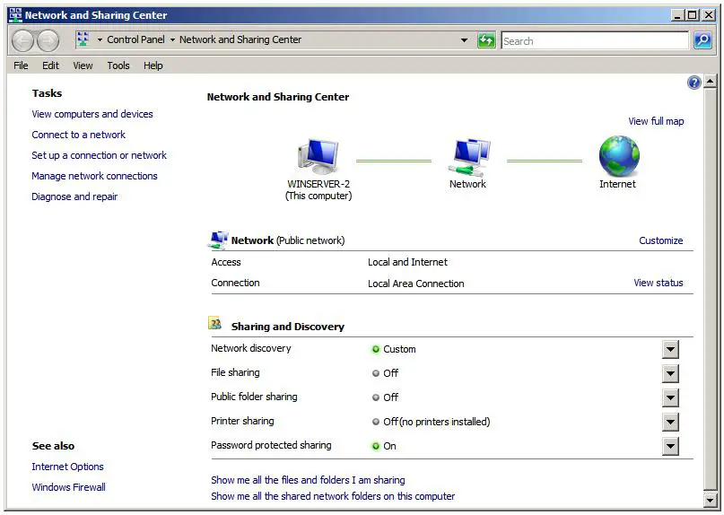
To enable public file sharing, click on the down arrow next to the Public folder sharing in the section entitledSharing and discovery. This will provide the following list of public folder sharing options:
  • Turn on sharing so anyone with network access can open files - Allows network users to open, but not delete, modify or create files in the server's public folder.
  • Turn on sharing so anyone with network access can open, change and create files - Allows network users to open, modify, delete and create files in the public folder.
  • Turn off sharing (people logged on to this computer can still access this folder) - Allow public folder access only to those users locally logged on to the server. Network users are denied access.
Similarly, standard file sharing can be configured by click the down arrow next to File sharing. When unfolded, this panel provides the option to either enable or disable standard file sharing on this server. When enabled, a dialog will appear providing the option to make the shared folders available only to the private network on which the system resides, or to make sharing available to public networks. The choice here depends on the requirements of the organization but for security purposes it is typically best to limit sharing to the private network unless external access is required.
The Network and Sharing Center also allows password access to shared folders to be configured. When the arrow next to Password protected sharing is selected the options to enable or disable password protection sharing are provided. When enabled on workgroup servers, only users with user accounts and passwords on the server will be able to access shared files and folders.

CREATING SHARED FOLDERS WITH WINDOWS EXPLORER

Shared folders can be configured using Windows Explorer, simply by navigating to the folder to be shared, right clicking on the folder and selecting Properties from the menu. In the properties dialog, click on the Sharing tab to display and modify the current shared folder settings as illustrated in the following figure:
Configuring the Windows Server 2008 folder sharing properties


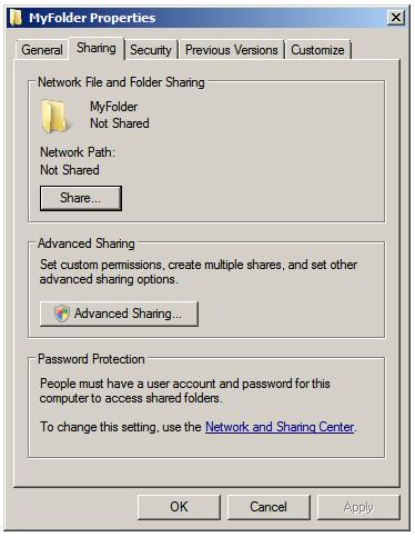
Within the sharing property panel, click on the Share... button to access the 
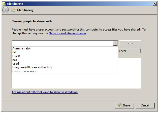
File Sharing dialog. Within this dialog, the users who may access this shared folder are specified. If file sharing has been restricted to users with local accounts and passwords, a list of users can be obtained by clicking on the down arrow. In this situation, select and add users, or select Everyone if access is to be made available to all users with local accounts:

Selecting which users have share access to a folder

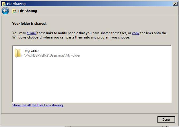
Once these settings are complete, click on the Share button to initiate the file sharing process. Once this initial phase of the share setup is complete a dialog will appear announcing this fact, listing the full Universal Naming Convention (UNC) path to the shared folder and providing the option to email users to notify them of this fact:

Selected folder is now shared

Having specified which users will have access to the folder the next step is to enable the sharing of the folder, specify share permissions and configure a Share Name by which the folder will be referenced and accessed. In addition caching of shared files can be configured. Caching allows users to maintain local copies of shared files so that they can be accessed off-line (for example when the server hosting the files is not available to the user's local system). With caching configured, local copies of shared files are stored on the user's local system so that they can be accessed without a connection to the server. When a connection is re-established, any changes made to the local copy of the file are synchronized with the original copy on the server.
To configure these settings, click on the Advanced Sharing button to display the following dialog:


Configuring advance file and folder share settings

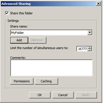
In this dialog, set the Share this folder option to enable the sharing of the folder. Once this has been selected the Share name field and associated button will activate enabling a share name to be entered. By default the name of the folder being shared will be displayed, although this may be changed to another name if desired. If the number of concurrent users accessing a shared folder is of concern, modify the number of simultaneous users accordingly. Enter optional comments about the share before clicking on 
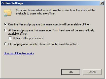
Caching to configure the off-linefile settings. This will invoke the Offline Settings dialog where a number of options are available including allowing each user to specify which files they would like to be able to access off-line, only having files that users actually access available off-line and disabling off-line sharing all together:

Configuring Windows Server 2008 offline (cached) file sharing

The final step in the folder sharing setup is to click on Permissions to configure the share permissions, details of which are covered in a later section of this chapter.

CREATING SHARED FOLDERS ON REMOTE SERVERS WITH COMPUTER MANAGEMENT

Windows Explorer provides an excellent mechanism for configuring shares on the local system. This approach falls a little short in terms of convenience, however, when it is necessary to configure shares on a remote server. Fortunately Windows Server 2008 addresses this need by allowing shares to be configured from theComputer Management tool. One point to note is that while this section will focus on the remote configuration of file shares, the steps outlined here may equally be used to share files on a local server. In fact, the Create a Shared Folder Wizard can be invoked on a local machine either from Computer Management or by enteringshrpubw at the command prompt or in a Run dialog.
After starting Computer Management on the local system, right click on Computer Management in the left panel tree and select Connect to another computer... In the resulting dialog box either enter the name of the remote computer or click on Browse and then Advanced... to search the network or domain for the remote system. Once a connection has been established to the remote server the Computer Management interface will refresh and the Computer Management link in the tree will also display the name of the selected remote server.
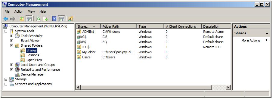
Once Computer Management is configured to administer a remote server, the next step is to begin the folder sharing process. Begin by unfolding the System Tools, then Shared Folders branches of the tree in the left panel. Select Shares to obtain a list of current shares configured on the remote system. The following figure illustrates Computer Management with a list of shares configured on a remote system named WINSERVER-2:

The list of shared folders on a remote system

The creation of a new shared folder on the remote server (although as previously mentioned this can also be used on local computers) involves the use of something called the Create A Shared Folder Wizard, which, as the name suggests provides a user friendly way of configuring shared folders. To invoke this wizard, simply right click on New Share..., then click on Next on the wizard's welcome screen. In the resulting Folder Pathscreen, either type in the path of the folder to be shared, or browse the file systems to locate it. With the required folder path selected click on Next to configure the name and description settings. On this screen, specify the share name by which the folder will be accessed from remote computers together with an optional description of the shared folder. Next, configure the off-line file settings for the folder contents by clicking onChange.
Once these settings are configured, click on Next once again to configure the share permissions for the selected folder. Either select one of the pre-configured options or select Customize permissions and click onCustom to configure share permissions on a per user basis.
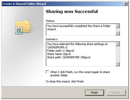
Finally, click on finish to complete the sharing process. If the configuration is successful a summary screen similar to the one illustration in the following figure will be displayed:

Successful sharing of folder

CREATING HIDDEN SHARES

By default, shared folders are listed when users browse for shared resources. From time to time, however, it may be necessary to share a folder but have it hidden such that only users who know of its existence can access it by referencing the share name. This concept is known as hidden share access. The most important point to note about hidden shares is that it does nothing to prevent access other than hiding the fact that the share exists. If, for example, a user learns of the existence of a hidden share (perhaps because another user tells them about it), and the share permissions are such that they have access to the folder, the fact that it is hidden will do nothing to keep the user out of that folder.
Shares are made hidden by placing a $ at the end of the share name. For example, to hide a share located at C:\accounts simply give it a share name with a trailing $, such as accounts$.

UNDERSTANDING AND CONFIGURING SHARE PERMISSIONS

As outlined at the beginning of this chapter, Windows Server 2008 provides two levels of permissions for shared files and folders, namely share permissions and file and folder permissions. Share permissions are applied when access is made via the network. When shared files and folders are accessed locally from the server on which they reside these permissions serve no purpose. File and folder permissions, on the other hand, take effect both when accessing files and folders both locally and over the network. In the case of network access to shared files and folders, the shared permissions are applied first, followed by any file and folder permissions. The key issue to note is that file and folder permissions provide a far greater level of control over access than the more general permissions options provided by share permissions. In this section, share permissions will be covered. For details on file and folder permissions refer to the chapter entitledUnderstanding Windows Server 2008 File and Folder Ownership and Permissions. 
Share permissions are granted on a per user and per group basis. In addition to allowing a cap on the number of concurrent users accessing a share to be defined, share permissions also provide three permission options, each of which can be set to Allow or Deny:
  • Full Control - Grants the specified users permission to change file and folder permissions, execute, read, modify, create and delete files and sub-folders.
  • Change - Grants users permission to change file and folder attributes, read, modify, execute, create and delete files and sub folders.
  • Read - Grants users permission to read and execute files and view and access file lists and sub-folders.
Permissions are cumulative in that a user will inherit the permissions of all the groups of which he or she is a member. If a permission is Denied, however, it overrides any cases where that permission may have been granted. For example, if a user is a member of a group where full control is provided over a folder, and also a member of a second group where full control is specifically denied, the user will be denied full control regardless of the fact that it was granted in the first group.
To configure share permissions, start Computer Management, connect to a remote server if not working on local shares, unfold System Tools and select Shares to list all currently shared folders. To configure share permissions for a folder, select it from the list, right click and select Properties. In the properties dialog select the Share Permissions tab as illustrated in the following figure:

Configuring Share Properties on a Windows shared folder

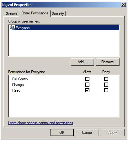
This screen displays the current share permissions and provides the ability to configure additional permission controls. To change the settings for a currently configured group or user select the user from the list, modify the permissions accordingly and click on Apply to commit the changes.
To add permissions for a specific user or group click the Add button and enter one or more users or groups into the text box (separating multiple entries with a semi-colon) and click on Check Names to verify the names are correct. Click on OK to return to the properties dialog where the added users and groups will appear in the list. Once again, select each name in turn and configure the desired share permissions. Finally, click Apply to commit the new permissions.

How to Create Hotspot ?


How to Create Hotspot

Linksys WRT54GL
Linksys released the WRT54G router in 2002. It gained popularity for being a powerful, easily customizable router. Several third-party projects have released replacement firmware for the router which can enable it to perform functions not originally available. It important to buy a Linksys WRT54GL as it has enough memory to install the third-party firmware. Recent version of the WRT54G have too little memory so make sure you go for the WRT54GL.
OpenWRT and X-WRT
OpenWRT is a Open Source firmware project for the WRT54GL router. It's a very small version of Linux which runs in place of the stock Linksys firmware. The firmware is available from openwrt.org. I prefer to use another project called X-wrt (x-wrt.org) which is based on OpenWRT but has added a nice graphical front end for configuring the router.
To install X-WRT (Which may void your warranty)
1) Download the openwrt-wrt54g-squashfs.bin firmware image to your PC
2) Open [http://192.168.1.1/Upgrade.asp] in your browser or manually go to
[http://192.168.1.1] -> Administration -> Firmware Upgrade
3) Upload openwrt-wrt54g-2.4-squashfs.bin
4) Wait 2 minutes. The router will reboot itself automatically after the upgrade is complete.
5) You should now be able to telnet to your router (IP address: 192.168.1.1) and start configuring.
Installing a Captive-Portal.
Nearly all commercial Hotspots are Captive Portals, this appears as an Open or Unencrypted Wifi signal but then redirects any traffic to a specific web page called a "Splash Page" where your often asked to login or purchase internet access. This is a clever way of doing things as most laptops will automatically connect to an open WiFi signal, then when a customer runs Internet Explorer (or which ever Web browser they use) they are sent to your splash page no matter what site they try to connect to. The most well known free captive portal software is Chillispot, which can be downloaded, and set-up, alternatively a number of commercial providers produce easy to use Captive Portal software, which can be installed on your WRT54GL.
Summary
In this article we have look at how powerful and versatile the Linksys WRT54GL router is. With a bit of work you can convert it into a powerful WiFi Hotspot router, which can be used for billing your customers for Internet access. Good luck with you new project!
UseMyNet sell Wireless Hotspot software that turns a Linksys WRT54GL router into a self-contained WiFi Hotspot. UseMyNet WiFi Pay solutions can provide additional revenue ideal for Pubs, Hotels and B&Bs

Configuring the Hotspot Server


Configuring the Hotspot Server

CONFIGURING THE HOTSPOT SERVER

First, make sure that you configured the Internet connection on its interface and created an IP on another interface for the LAN/hotspot. (We discussed this in Part 1 of this tutorial series.)
Now you can configure a hotspot server on the LAN/hotspot interface with the WinBox utility. Follow these steps:
  1. Click IP > Hotspot.
  2. Click the Hotspot Setup button to open the wizard.
  3. Select the interface that the switch or AP for the hotspot network will be connected to and then click Next.
  4. Verify the IP of the server, which should be the address you had created for the LAN/hotspot interface, and click Next.
  5. Verify the IP range that's automatically chosen for the hotspot users and click Next.
  6. Ignore the server certificate setting, at least for now, and click Next.
  7. It's best to secure your hotspot login pages with SSL encryption when users are logging in with unique accounts; otherwise, the account credentials could be easily sniffed by eavesdroppers on the network. When accepting payments, encryption is a must! You'll see how to get this all set up a bit later.
  8. Unless you are running your own SMTP email server or are using a service, ignore the setting and click Next.
  9. To prevent people from sending junk or illegal email from your Internet connection, you should block the port used for outgoing email (25), which I'll discuss later. However, so users aren't forced to use only web-based mail applications, you can list your own SMTP server that better controls usage, preventing them from sending tons of email.
  10. Verify that the DNS server address from your Internet connection is entered and click Next.
  11. If you prefer that your users see a DNS (domain) name instead of the gateway's IP when logging in, you can create one here and click Next.
  12. You can essentially just make up a domain name, such as hotspot.yourcompanyname.com. If nothing is entered, your IP address will automatically be used.
  13. Finally, create a hotspot user so you can log in; then click Next.
After completing the Hotspot Setup Wizard, you should get a disconnect prompt from WinBox. That means the hotspot captive portal is working. To receive network and Internet access, you must log in with the account you created via the Web browser.

Cisco RV 120W Wireless-N VPN Firewall


Cisco RV 120W Wireless-N VPN Firewall


Take Basic Connectivity to a New Level
The Cisco® RV 120W Wireless-N VPN Firewall combines highly secure connectivity - to the Internet as well as from other locations and remote workers - with a high-speed, 802.11n wireless access point, a 4-port switch, an intuitive, browser-based device manager, and support for the Cisco FindIT Network Discovery Utility, all at a very affordable price. Its combination of high performance, business-class features and top-quality user experience takes basic connectivity to a new level (Figure 1).
Figure 1. Cisco RV 120W Wireless-N VPN Firewall
Product Overview
The Cisco RV 120W Wireless-N VPN Firewall features:
• High-speed, standards-based 802.11n wireless connectivity to help employees stay productive while away from their desks
• Integrated 4-port 10/100 switch with quality of service (QoS) support for enhanced voice, video and data traffic
• Support for separate "virtual" networks enables you to control access to sensitive information and to set up highly secure wireless guest access
• IP Security (IPsec) VPN support with hardware acceleration to deliver highly secure, high-performance connections to multiple locations and traveling employees
• Support for static routing, Routing Information Protocol (RIP) versions 1 and 2, and inter-VLAN routing to enable flexible connection sharing
• Proven stateful packet inspection (SPI) firewall, plus advanced wireless security to help keep business assets safe
• Simplified configuration through an intuitive, browser-based device manager
• Support for the Cisco FindIT Network Discovery Utility
Figure 2 shows back panel of the Cisco RV 120W. Figure 3 shows a typical configuration using the firewall.
Figure 2. Back Panel of the Cisco RV 120W
Figure 3. Typical Configuration
Product Specifications
Table 1 gives the product specifications for the Cisco RV 120W.
Table 1. Product Specifications
Feature
Description
Routing
• Static routing
• RIP v1 and v2
• Inter-VLAN routing
Layer 2
• 802.1q -based VLANs
• 4 active VLANs (1 to 4094 range)
Network
• Dynamic Host Configuration Protocol (DHCP) server, DHCP relay agent
• Point-to-Point Protocol over Ethernet (PPPoE), Point-to-Point Tunneling Protocol (PPTP), Layer 2 Tunneling Protocol (L2TP)
• DNS Proxy
• IGMP Proxy and multicast forwarding
• Dynamic Domain Name System (DynDNS, TZO)
• Network Address Translation (NAT), Port Address Translation (PAT), Network Address Port Translation (NAPT), Session Initiation Protocol Application Layer Gateway (SIP ALG), NAT traversal, one-to-one NAT
• Multiple DHCP pools
• Port Management
IPv6
• Dual-stack IPv4 and IPv6
• Multicast Listener Discovery (MLD) for IPv6 (RFC2710)
• Stateless address auto-configuration
• DHCP v6
• Internet Control Message Protocol (ICMP) v6
Security
Access control:
• IP access control lists (ACLs)
• MAC-based wireless access control
Firewall:
• SPI firewall
• Port forwarding and triggering
• DoS prevention
• Software based DMZ
Content filtering:
• Static URL blocking or keyword blocking
Secure management:
• HTTPS
• Username/password
802.1X
• Port-based RADIUS authentication (Extensible Authentication Protocol [EAP], Protected EAP [PEAP])
Certificate management
• X.509 v3 certificates
• Certificate upload using PEM format
VPN
• 10 QuickVPN tunnels for remote client access
• 10 IPsec site-to-site tunnels for branch office connectivity
• Triple Data Encryption Standard (3DES), Advanced Encryption Standard (AES) encryption
• Message Digest Algorithm 5 (MD5)/Secure Hash Algorithm (SHA1) authentication
• Dead Peer Detection (DPD)
• IPsec NAT traversal
• VPN pass-through of PPTP, L2TP, IPsec
Quality of Service
• 802.1p port-based priority on LAN port, application-based priority on WAN port
• 4 queues
• DiffServ support
• Traffic Metering
Management
• Simple Network Management Protocol (SNMP) versions 1, 2c and v3
• Event logging: local, syslog, email alerts
• Firmware upgradable through web browser; imported/exported configuration in text format
• Simple browser-based configuration (HTTP/HTTPS)
• UPnP, Bonjour
• Network diagnostics with packet captures
Performance
• NAT throughput: 95 Mbps
• 1000 concurrent sessions
• VPN throughput: 25 Mbps
Wireless LAN Specifications
Table 2 gives the wireless specifications for the Cisco RV120W.
Table 2. Wireless LAN Specifications
Feature
Description
WLAN hardware
IEEE 802.11n standard-based access point with 802.11b/g compatibility
Radio and modulation type:
• 802.11b: direct sequence spread spectrum (DSSS)
• 802.11g/n: orthogonal frequency division multiplexing (OFDM)
• 2 omnidirectional 1.8 dBi gain external antennas
Operating channels:
• 11 in North America
• 13 in most of Europe
• Automatic channel selection
Transmit power:
• 802.11b: 17 dBm +/- 1.5 dBm
• 802.11g: 15 dBm +/-1.5 dBm
• 802.11n: 12.5 dBm +/- 1.5 dBm
Receiver sensitivity:
• 802.11b: 11 Mbps@ -90 dBm
• 802.11g: 54 Mbps @ -74 dBm
• 802.11n: 270 Mbps @ -71 dBm
Wireless Domain Services (WDS):
• Allows wireless signals to be repeated by up to 2 compatible receivers
Wi-Fi Multimedia (WMM):
• WMM with QoS (802.11e)
• WMM Power Save (WMM-PS)
Active WLAN clients
• Up to 64 clients
Service Set Identifiers (SSIDs)
• Up to 4 separate virtual networks
Wireless VLAN
• Support for SSID to VLAN mapping with wireless client isolation
WLAN security
• Wi-Fi Protected Access (WPA2, 802.11i)
System Specifications
Table 3 gives the system specifications for the Cisco RV 120W.
Table 3. Table 3 System Specifications
Feature
Description
WAN
10/100 Mbps Fast Ethernet WAN port
LAN
4-port 10/100 Mbps switch with support for VLAN and QoS
WLAN
Built-in high-speed 802.11n wireless access point
Physical dimensions and weight
• W x D x H = 5.91 in. x 5.91 in. x 1.34 in. (150 mm x 150 mm x 34 mm)
• Weight: 1.10 lb (0.5 kg)
Power
12V 1A
Certification
• FCC Class B
• CE
• IC
• Wi-Fi
Environmental operating range
• Operating temperature: 0° to 40°C (32° to 104°F)
• Storage temperature: -20° to 70°C (-4° to 158°F)
• Operating humidity: 10% to 85% noncondensing
• Storage humidity: 5% to 90% noncondensing
Configuration Requirements
Table 4 lists the configuration requirements for the Cisco RV 120W.
Table 4. Configuration Requirements
Feature
Description
Network adapter
PC with network adapter and Ethernet cable
Web-based configuration
Web browser
Ordering Information
Table 5 gives ordering information for the Cisco RV 120W.
Table 5. Ordering Information
Part Number
Product Name
RV120W-A-NA
Cisco RV 120W Wireless-N VPN Firewall (USA)
RV120W-E-G5
Cisco RV 120W Wireless-N VPN Firewall (Europe)
RV120W-N-AU
Cisco RV 120W Wireless-N VPN Firewall (Australia)
RV120W-A-CN
Cisco RV 120W Wireless-N VPN Firewall (China)
RV120W-A-CA
Cisco RV 120W Wireless-N VPN Firewall (Canadian French)
RV120W-A-AR
Cisco RV 120W Wireless-N VPN Firewall (Argentina)
Warranty Information